|
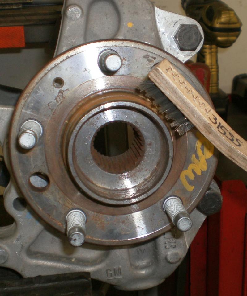
HUB PREP
Take a moment to clean the rust and build up off the hubs and the spindle mounting bosses before installing the hats and rotors. This will ensure that the hat is flush to the hub and has no debris under it which can interfere with it seating properly.
|
 |
|
ROTOR PREP 1
First step in assembling the hat to the rotor is to chase the threads in the rotor is so supplied.
The rotor is tapped 5/16-24 SAE and the post surface cut and zinc plate work can often plug up the threads making assembly difficult and mounting not square to the hat. Adding a drop of cutting oil to the tap and chase each hole before assembly will go a long way towards a satisfying hat and rotor fit.
Be sure to clean and dry the threads of any oil before final assembly.
|
|
|
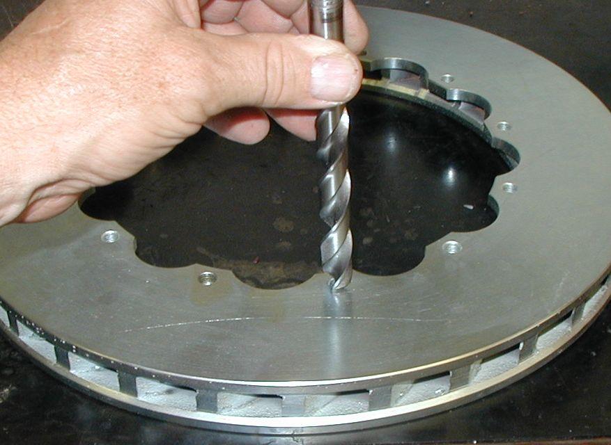
ROTOR PREP 2
After the threads are chased use either a debur tool or a large drill bit and lightly debur the hat mounting holes by hand to be certain there are no threads or burs on the edge of the holes. Any high spots may prevent the hat from seating flush to the rotor surface.
|
 |
|
ROTOR PREP 3
Run a quality flat file over both the outer edge and the scalloped inner edge of the rotor to be certain there are no nicks, burs or dents in the rotor surface. Even a small chip in the outer surface from being banged around on the workbench or floor can put a large enough dent in the rotor to be felt under light pedal pressure.
Run you finger and eyes over the entire surface before bolting to the rotor hat and address any small blemishes you find now as it's much easier now than once fit to the car.
Travel in the "Brown Truck" can lead to minor issues so look now.
|
|
|
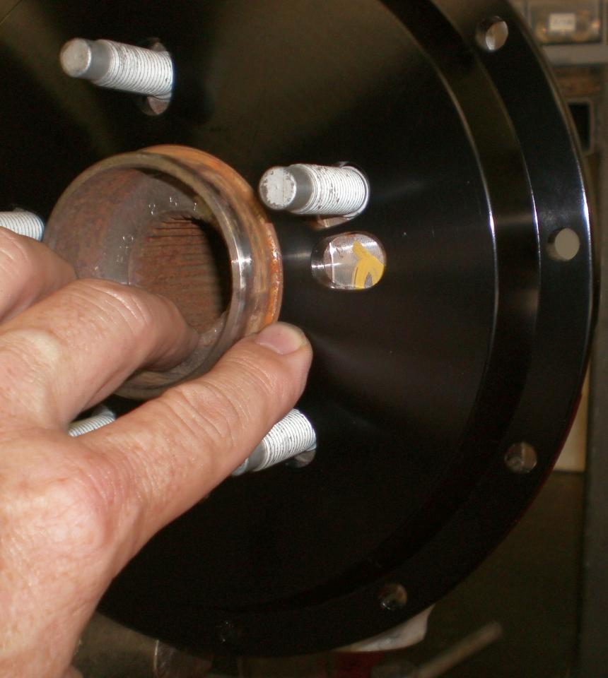
HAT PREP 1
Before securing the hat to the rotor take a moment to check fit the hats to your hub.
The hat should be centered on the hub with only a minimal amount of free play and not require that it be forced onto the hub. Be certain there is no interference between the hat and the hub at the stud knurl which at times can be slightly larger in diameter than the stud. If so you may need to chamfer the hat slightly to clear this protrusion.
Listen for a firm ring as they 'clunk' flush to the hub. If there is any wiggle on them this could indicate they are not seated fully.
|
 |
|
HAT PREP 2
Inspect and prep the rotor hat mount surface as you have the rotor; look for any nicks or burs that maybe evident on the mount surface preventing a smooth and flush fit when bolted in place.
|
|
|
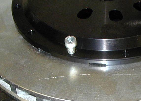
ROTOR/HAT 1
Place the rotor hat onto the flat side of the rotor and install all the socket head cap screws hand tight before torquing them. Apply a drop of Red Loctite to each bolt and cross tighten with a allen-head tee handle or wrench.
Kits that use Wilwood hats are threaded to the hat- if so supplied follow the same basic principals and the instructions supplied. Rear parking brake hats are shipped with one "mock up" hat and rotor for an assembly example. Final assembly will be as supplied.
|
 |
|
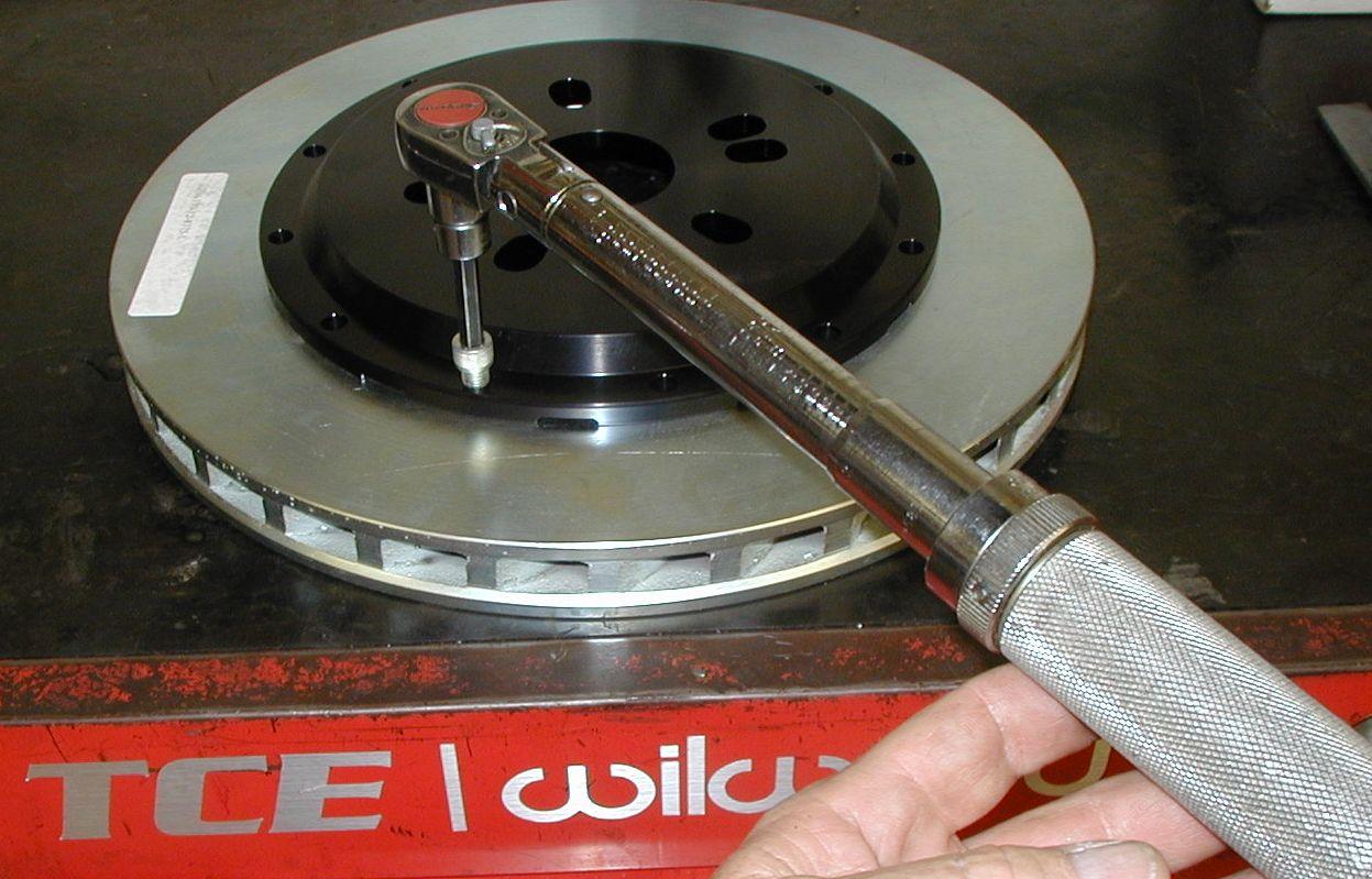
ROTOR/HAT 2
With the bolts in place and hand tightened go back and properly torque each bolt in a crossing pattern to the required specification.
Common TCE Hat torque: (5/16-24 SHCS) 21ft lbs.
* Hat torque can vary by design and type. See the instructions or call if you have any question about torque.
|
 |
|
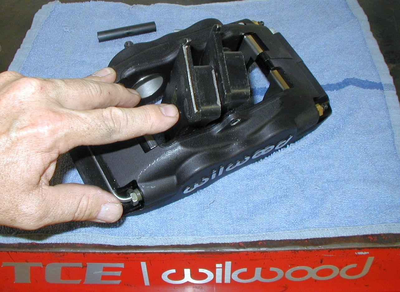
PAD INSTALL 1
Pads are held in place by the a Bridge Bolt and Stainless Steel tension clips. This clip serves double duty by preventing the pads from digging into the aluminum body of the caliper and to apply light tension to the pad to keep pad rattle to a minimum.
Over time the tension on these clips can weaken requiring they be either replaced or bent back to create the tension once again. If the caliper has excessive pad rattle or 'clicking' you can also remove the tension clip and apply a very small amount of silicone under the clip, replace it and then wait a couple of hours before fitting the pads again. This added tension will help keep both noise and vibration down as well as cushion the compression of the pad to the caliper body. The application should be very small so not to fill the gap preventing the pads from being installed however.
Replacement tension clips can be ordered off the SERVICE PARTS page.
|
 |
|
PAD INSTALL 2
Before final install of the pads it may be necessary to file the ends of the brake pad backing plates for them to fit without excessive force to the caliper body. Because the backing plates are stamped they often show what's called a 'kurf' to the ends-making the plate a bit wider on one end. This can make pad fit overly tight to the body of the caliper.
With a flat file gently square up the pad ends so they glide freely, but not loosely, into the caliper body. If you remove too much material they will be loose and noisy as they click from load to rest during the brake torque moment.
*This step is required when fitting pads to powder coated caliper bodies due to the build up of paint on the aluminum body.
|
 |
|
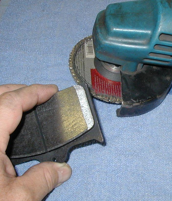
PAD INSTALL 3
To reduce both squeal and pad judder it's advised that the pads have a tapered leading edge ground or filed into them upon assembly. Competition pads are produced in a 'block' manner and don't come with this feature.
This can be accomplished with either a hand file, a sanding belt or an abrasive grinder as shown. Grind a bevel to the leading side only- that side which first contacts the rotor by way of its directional rotation. This feature will allow the pads to more freely glide over gas slots and holes and can reduce light pulsation and or vibrations caused by that contact.
|
 |
|
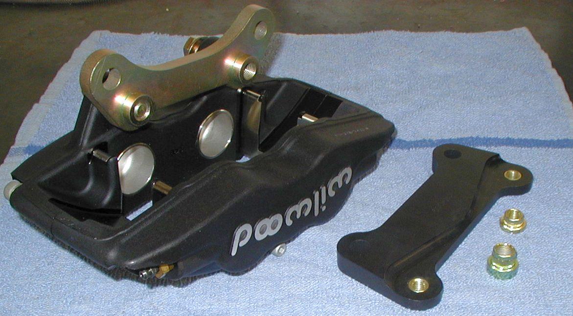
BRACKET INSTALL 1
Many TCE kits are supplied with steel or aluminum single plane brackets for the Lug Mount caliper design. These brackets are then fit with captive or Clinch nuts. The clinch nut takes the place of a conventional nut and is secured in place by a press fit and by the tightening of the retainer bolt. As the mounting bolt is tightened to the bracket the clinch nut has a shoulder which pulls tightly against the other side of the bracket.
Before installing the bracket be certain the bolts pass freely and do not require the threads be chased with a tap- this should be completed prior to shipping. There are two sizes: 3/8-24 SAE and 7/16-20 SAE should you need to tap them. Be certain the threads are free of oil and debris before final assembly and Loctite is added. Also be certain the bolts or the clinch nuts themselves do not contact the inner side rotor surface. Some applications may require an additional washer under the bolt head to prevent bolt to rotor contact.
Torque: 3/8-24: 38-40ft lbs & 7/16-20: 45-50ft lbs.
|
 |
|
BRACKET INSTALL 2
TCE Radial brackets should have a thin coating of Anti-seize smeared over the stud to prevent corrosion between the steel stud and aluminum caliper body. This also make installation and removal much easier in the future. A small amount on the thread is acceptable for those racing applications where the caliper maybe removed regularly for rotor service. If done so adjust the stated torque value down accordingly for the lubricated thread. For street applications no Anti-seize is necessary on the thread and a tab of Red Loctite will suffice as removal of the caliper body is less frequent.
|
 |
|
CALIPER SHIMMING 1
All calipers must be shimmed "on center". Meaning the center line of the caliper should be equal to the center line of the rotor. This is established by the caliper mount bracket and its related barrel spacers and/or stainless steel shims. Shimming can be done between the caliper ears and bracket or between the spindle ears and bracket depending upon what movement is required. Exact centering is not overly critical and comparing one pad fit to the rotor to the other pad should be a good gage.
Your kit should allow for a minimal amount of adjustment to compensate for any spindle variations. Supplied shims should be ample for the need. Shimming may also be different from one side of the vehicle to the other at time- this is especially true on rear kits were axle locations can have an impact on rotor placement relative to the mount bracket.
|
|
|
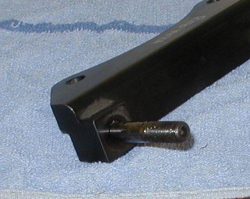
CALIPER SHIMMING 2
For those kit supplied with billet aluminum radial mount brackets (studded spars shown above) shimming the height or radius of the pad and caliper are adjusted by the fit or removal of shims on the stud. Radial shims allow for various rotor diameters be fit to the same bracket so some kits may have a longer stud and round barrel spacer be slipped onto the stud then followed by shims.
Radial shims are supplied in both .030" and .015" allowing a wide range of adjustment. Vary the shim stack until the edge of the pad is flush to the edge of the rotor and then secure it with the cap nut and washer. Shimming must be equal on both studs to keep the caliper square to the rotor.
|
|
|
"AN" ADAPTER INSTALL
Wilwood calipers come with a 1/8"npt (national pipe thread) inlet on the inboard side of the caliper. Your kit is supplied with adapter fittings for the fit of -3AN Stainless Steel braided hoses.
Install the adapter fitting as shown using a small amount of Teflon tape or similar Teflon sealant. Apply this to the larger end of the fitting leaving the cone end dry for the hose to be fit too.
The adapter fitting should be tightened down about half way on down its thread. This can be done with a 7/16 box wrench or socket. If checking torque the net result is about 11ft lbs. Pipe thread is tapered however so it can be forced in deeper if you continue to turn it. Some kits may be supplied with 45 or 90 degree fittings which will require you "point" or "index" the nipple to it's final location.
|
 |